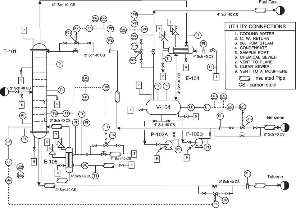
Piping and instrumentation diagram of the humidistat. Starting from the
Price: $ 61.00
4.6(680)
Download scientific diagram | Piping and instrumentation diagram of the humidistat. Starting from the left, pressure-regulated dry nitrogen is fed into the device. The stream is split into two. One of the streams is humidified, while the other is not. Solenoid valves inserted in the streams modulate the flow rates of humidified and dry nitrogen, after which they are combined again and led into the chamber. A controller acting on the humidity in the chamber sets setpoints of flow controllers that determine the ratio of humid and dry flows. PI, TI, FC, and HC stand for pressure indicator, temperature indicator, flow controller, and humidity controller, respectively. from publication: OpenHumidistat: Humidity-controlled experiments for everyone | Humidity control is a crucial element for a wide variety of experiments. Yet, often naive methods are used that do not yield stable regulation of the humidity, are slow, or are inflexible. PID-based electropneumatic humidistats solve these problems, but commercial devices are | Humidity, Humidity Sensors and Air Flow | ResearchGate, the professional network for scientists.

HVAC Ducting and Instrument Diagram (D&ID / P&ID)

Wiring and Setting of Humidistat/Dehumidistat in Humid Climates

Wiring and Setting of Humidistat/Dehumidistat in Humid Climates

Piping & Instrumentation Diagrams Guide
What is a Piping and Instrumentation Diagram (P&ID)

Federal Register :: Energy Conservation Program for Certain
Piping and Instrument Diagrams (P&IDs): Part 1 - Becht

OpenHumidistat: Humidity-controlled experiments for everyone
What Is Piping And Instrumentation Diagram (P&ID)

Piping and instrumentation diagram - Wikipedia

OpenHumidistat: Humidity-controlled experiments for everyone
1.3. Piping and Instrumentation Diagram (P&ID)

HVAC Ducting and Instrument Diagram (D&ID / P&ID)

Piping & Instrumentation Diagrams Guide

:max_bytes(150000):strip_icc()/nutrichef-nonstick-cookie-sheet-baking-pan-set-tout-XL-AFF0922-2000-c403b48e3bfc49368bf9c159f9fd3112.jpg)